
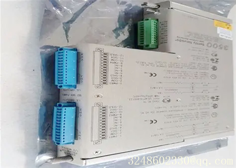
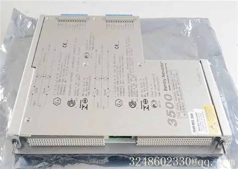

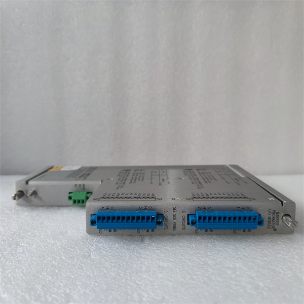
Bently Nevada 135489-02(3500/42M) I/O Module
Warranty: 365 days
Quality: Original module
Condition: New / Used
Warehouse: Spot
Delivery time: Shipped in 3 days after payment
WhatsApp:+86 18030183032
Mailbox:3248602330@qq.com
product description
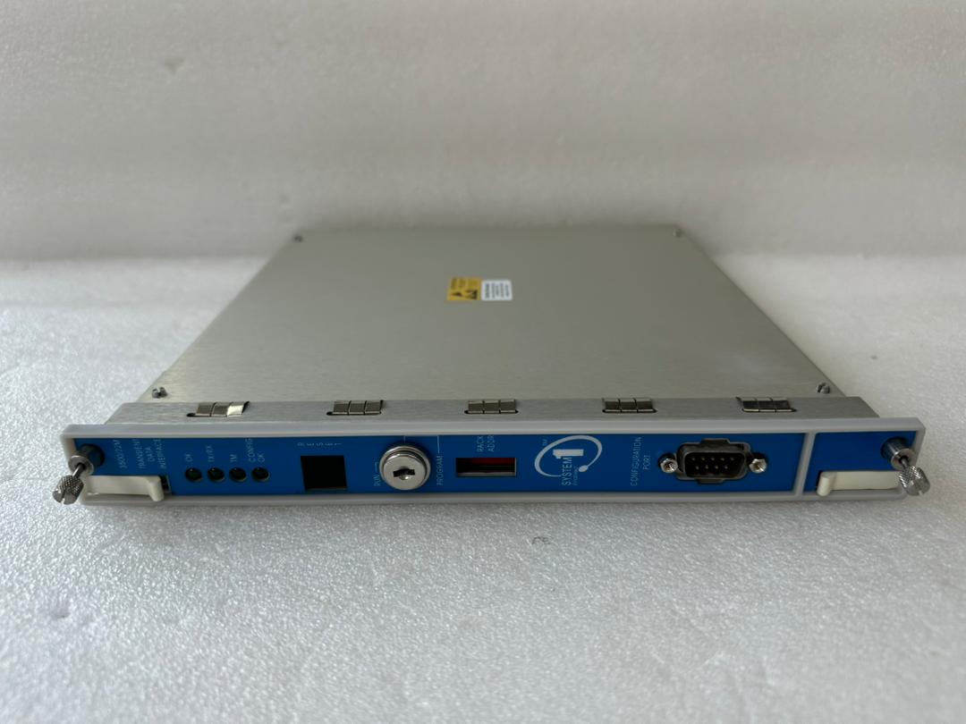
Bently Nevada 135489-02 (3500/42M) is an I/O module with internal safety barriers designed specifically for 3500 mechanical protection systems.
1. Core configuration
It adopts a channel combination of 2 x displacement/acceleration+2 x speedometer, with built-in internal terminals and intrinsic safety barriers, suitable for signal processing of vibration and displacement sensors in hazardous industrial environments.
2. Key characteristics
Supports communication with Modbus, Ethernet, and SCADA systems, with RS-232/422 communication response time less than 0.5 seconds.
Equipped with ATEX and IECEx explosion-proof certifications, it can be used in Class 1 Zone 2 hazardous areas in compliance.
It needs to be paired with a 3500/42M front-end monitor and cannot be operated as a standalone module.
3. Basic parameters
The power supply is 24V DC, with a standard market reference price of about $2300 and a standard weight of 0.4kg. It is installed in a rack and compatible with 3500 system racks.
Based on the usage scenario of the 3500/42M 135489-02 module mentioned earlier, the following provides you with a complete wiring diagram and step-by-step configuration operation guide:
1、 135489-02 Module Wiring Diagram Explanation
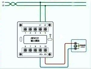
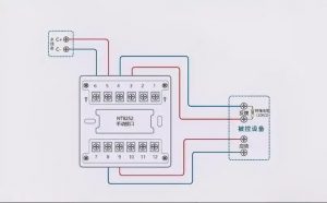
Intrinsic safety side (hazardous area) wiring
Two displacement/acceleration channels: connected to eddy current displacement sensors and piezoelectric acceleration sensors respectively, with signal terminals connected to the local safety end of the internal safety barrier and single end grounding of the shielding layer.
2-channel speedometer channel: Connect the magneto electric speed sensor, pay attention to distinguishing the positive and negative poles of the signal, and avoid phase reversal that may cause monitoring data deviation.
Non intrinsic safety side (safe zone) wiring
The power supply terminal is connected to the 24V DC power supply of the 3500 rack, and the power supply voltage needs to be stable within the range of -23.7 ± 0.5VDC.
The communication terminal is connected to the RS-232/422 bus and is daisy chained to the 3500/20 framework interface module. The length of the communication cable does not exceed 1220 meters.
The 4-20mA analog output terminal is connected to the corresponding AI channel of the DCS system to achieve remote transmission of vibration/displacement data.
2、 Step by Step Configuration Operation Guide
Preliminary preparation
Install the official configuration software for the 3500 system, connect the 3500 framework through the RS-232 configuration port, and switch the framework key lock to program programming mode.
Basic configuration of module channel
Right click on the corresponding slot in the configuration software, select module model 135489-02, and activate all 4 monitoring channels.
Channels 1 and 2 are set to Radial Vibration/Thrust Position axial displacement mode, and the sensor type is selected to correspond to the Bentley eddy current sensor model.
Set channels 3 and 4 to Velocity monitoring mode, matching the sensitivity parameters of the connected magneto electric speed sensor.
Parameter calibration and alarm settings
Enter the custom option, switch from imperial units to metric units, and set the corresponding range (such as vibration range 0-500um pp).
Uncheck the alarm interlock Alert Latching and hazard interlock Danger Latching, and set the alarm delay to 1 second uniformly.
According to the protection setting requirements of the unit, set the alarm value and danger value for each channel separately, and select the corresponding alarm channel to enable.
Configuration download and verification
After confirming that all configurations are correct, download the configuration parameters to the 3500 framework and switch the key lock back to run mode.
Check the status of the OK indicator light on the front panel of the module, confirm that there are no alarms, and simulate the input of standard signals to verify the accuracy of channel monitoring values.

Reviews
There are no reviews yet.