
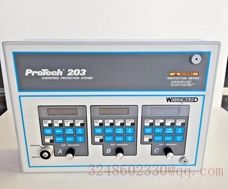

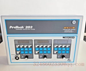
WOODWARD 8200-205 overspeed protection controller
product description
WOODWARD 8200-205 is a digital overspeed protection controller produced by Woodward Corporation in the United States. This device belongs to the ProTech series and is mainly used to monitor the speed of the prime mover and activate the trip relay when overspeed is detected, thereby preventing the prime mover from losing control or being damaged.
The following is a detailed analysis of the product:
1. Core functions and working principles
Independent safety protection: As an overspeed shutdown device, it must operate completely independently of the conventional control system of the prime mover, specifically designed to prevent personal injury, death, or property damage caused by overspeed of the prime mover.
Continuous monitoring and triggering: continuously sensing the speed of the prime mover through components such as magnetic sensors (MPU). When the system detects that the speed exceeds the normal parameter range, it will immediately activate the internal trip relay to perform an emergency stop.
Fault indication and alarm: equipped with remote reset and alarm output functions. The panel is equipped with separate LED indicator lights, which can intuitively display issues such as MPU faults, CPU functional abnormalities, or speed sensing unit tripping, to achieve rapid response.
2. Core technical features
High reliability design: Adopting a multi redundant and independent speed sensing unit architecture to ensure reliable protection mechanisms even under extreme working conditions.
Anti tampering and secure locking: Equipped with button locking function (such as key lock), the system can be placed in monitoring or programming mode. This single key locking method ensures that the entire system is set to the same mode simultaneously, easily preventing unauthorized changes.
Strong environmental adaptability: It has excellent industrial grade protection standards (such as IP54 and NEMA 4/4X levels) and can work stably in a wide temperature range.
3. Installation and wiring specifications
To ensure the long-term stable operation of the controller, the following requirements must be strictly followed during installation and wiring:
Location selection: A location with sufficient ventilation for cooling and maintenance space should be selected; It is necessary to prevent direct contact with water, avoid vibration, and stay away from high voltage, high current, or equipment that generates electromagnetic interference.
Power protection: To maintain a stable power supply voltage, the power cord should be protected with a 5A current. In addition, the fuse design inside the device can withstand surge applications for a certain period of time.
Shielding and grounding: The wiring terminals should provide shielded terminals for each signal, and all inputs should be wired using shielded twisted pair wires. The length of the wires outside the shielding layer should be limited to within 25 millimeters and terminated only at one end to avoid forming a grounding circuit.
4. Maintenance and safety precautions
When carrying out daily maintenance and operation of equipment, please pay attention to the following matters:
Electrostatic discharge protection: Electronic controllers contain electrostatic sensitive components. Before disposing or replacing the controller, be sure to discharge static electricity from your body (ensure the power is turned off and grounding measures are taken), and avoid placing plastic, plastic, foam and other materials around the printed circuit board.
Personal protective equipment (PPE): Always wear appropriate PPE when performing related work, including but not limited to eye protection, hearing protection, helmets, gloves, safety boots, and respirators.
Preparation before starting: When starting an engine, turbine, or other type of prime mover, emergency shutdown preparations must be made in advance to prevent loss of control or overspeed accidents.

Reviews
There are no reviews yet.